|
The components of the gears are made from alloy steel, casehardened according to standards IHA F154 and F156 for gear pinions, which have core breaking strengths of 120 and 130 Kg/mm². For the gear wheels, F155 and F158 steels are used, with respective breaking strains of 95 and 110 Kg/mm². The surface hardness of both pinions and wheels is maintained at 60-62 HRC, and each gear is finely ground on the flanks using high-precision equipment.
In bevel gears or perpendicular shaft setups, a Gleason-type spiral bevel is used. The pinion is constructed with F156 steel, providing a breaking strength of 130 Kg/mm², while the wheel uses F158 steel, offering a strain capacity of 110 Kg/mm². Both gears undergo case hardening, quenching, and lapping for smoother operation and minimal vibration.
The gears are carefully calculated for optimal strength and operational life, with permissible stress levels that remain well within the yield limits of the chosen materials.
Supports and Shafts
The shafts are crafted from IHA F155 alloy, which offers a core breaking strain capacity of 95 Kg/mm².
For the input shaft, a unified gear pinion and shaft design is used, with materials selected from either F153 or F156 alloy for maximum resilience. Each shaft is set within high-quality, precision bearings of ample size, with all seatings ground to exact tolerance specifications.
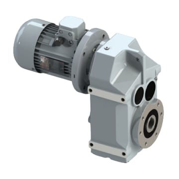
The gear reducer’s output shaft is hollow, designed to accommodate one-piece shafts that vary in shape and length according to requirements. Single or twin output shaft options are also available upon request.
Sealing
To maintain a waterproof seal, the unit uses ring seals made of acrylonitrile-butadiene rubber. For applications involving elevated temperatures, these can be substituted with VITON seals made from synthetic fluorine rubber.
Lubrication
|
Speed reducers of types 0 and 1 are supplied with polyolefin-based synthetic oil according to ISO VG 320, making them fully sealed and able to operate in any orientation. From type 2 onwards, reducers are shipped without oil, so the user is responsible for topping them up and must specify the mounting position to correctly place the filling, level, and drain plugs.
A manual with maintenance and lubrication instructions accompanies each device.
Power and Efficiency
|
The power levels provided in the selection table are intended for use in continuous, even load applications of up to 10 hours per day, without any impact loads or excess strain.
When different working conditions exist, it’s essential to refer to the tables in this catalog to find the suitable work factor for each specific application.
Each gear reducer’s efficiency rating depends on the number of reduction stages. For the RO and CRO series gear reducers, the efficiency ranges from 98.5% to 99% per reduction stage.
Reinforced bearings and Non-Returm
This series features bearings on the input and output shafts that are engineered to support supplementary external loads adequately. In cases of exceptionally high loads, it is possible to install bearings from higher-capacity series. Furthermore, these gear reducers can be provided with non-return mechanisms, which enable rotation in a single direction and prevent torque from being transmitted in the reverse direction.
|
|
|
