|
The gears within these speed reducers are manufactured from casehardened alloy steel that adheres to standards IHA F154 and F156 for gear pinions, providing core breaking strains of 120 and 130 Kg/mm², respectively. The gear wheels use steel per IHA F155 and F158, with a core breaking strain of 95 and 110 Kg/mm². Both pinions and wheels achieve a surface hardness of 60-62 HRC and are precision-ground to maximize accuracy.
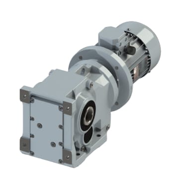
In perpendicular shaft reducers, the spiral bevel gears employ a Gleason design. The pinion is crafted from F156 steel, offering a core breaking strain of 130 Kg/mm², while the wheel, made of F158 steel, has a strain limit of 110 Kg/mm². Both components undergo case hardening, quenching, and lapping to reduce operational vibration.
The gears’ design is meticulously calculated for durability and efficiency, using load factors within the selected material limits to ensure long-lasting performance.
Supports and Shafts
The shafts in these speed reducers are manufactured using IHA F155 alloy, known for its core breaking strain of 95 Kg/mm².
The input shaft integrates a one-piece design combining the gear pinion and shaft, using either F153 or F156 alloy for enhanced durability. Each shaft is installed with top-quality precision bearings that offer generous dimensions, and the seatings are ground precisely to meet tolerance standards.
The output shaft is hollow, allowing the installation of customized one-piece shafts with specific shapes and lengths. Additionally, single or dual output shafts can be provided upon request.
Sealing
The unit’s watertight integrity is ensured by acrylonitrile-butadiene rubber ring seals. For operations involving high temperatures, these seals are replaced with synthetic fluorine rubber (VITON) for enhanced durability.
Lubrication
|
Type 0 and 1 speed reducers are prefilled with polyolefin-based synthetic oil compliant with ISO VG 320, ensuring they are entirely oil-tight and suitable for installation in any position. Starting from type 2, the reducers are delivered without oil, with topping up being the user’s responsibility. The user should also specify the mounting position to determine the location of the filling, level, and drain plugs.
Each unit comes with a maintenance and lubrication instruction manual.
Power and Efficiency
|
The power ratings shown in the selection table apply specifically to uniform workloads with up to 10 hours of operation per day, free from shocks or overloading.
For other operational conditions, consult the tables in this catalog to determine the appropriate work factor for the application.
The efficiency of each gear reducer is determined by the number of stages or reduction gear trains. For reducers in the RO and CRO series, each reduction stage operates at an efficiency of 98.5% to 99%.
Reinforced bearings and Non-Returm
The bearings incorporated in this series for the input and output shafts are designed to accommodate additional external loads effectively. However, in situations involving particularly heavy loads, bearings from higher-capacity series can be installed. Additionally, these gear reducers can be equipped with one-way devices that allow rotation in only one direction while maintaining the torque to be transmitted in the opposite direction.
|
|
|
